


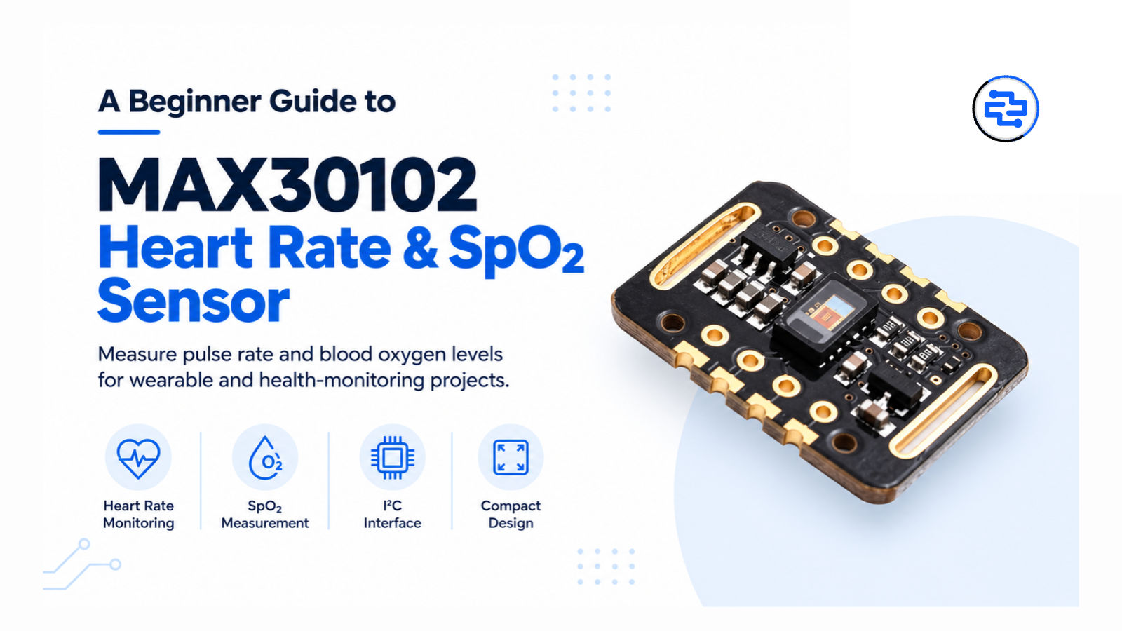
MAX30102 Heart Rate Sensor Module – Features & Uses | Directronics
Learn about the MAX30102 Heart Rate and Pulse Oximeter Sensor Module, including its key features, working principle, specifications, pinout, and applications. Discover how to use the MAX30102 with Arduino and ESP32 for heart-rate monitoring, SpO₂ estimation, wearable electronics, and IoT projects.
MAX30102 Heart Rate and Pulse Oximeter Sensor Module: Features, Specifications & Applications
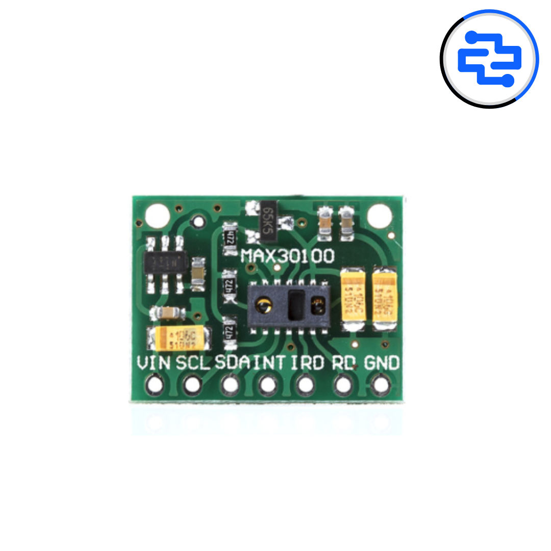
The MAX30102 Heart Rate and Pulse Oximeter Sensor Module is a compact optical sensing solution used to develop projects that measure heart rate and estimate blood oxygen saturation (SpO₂). It is commonly used in wearable electronics, fitness monitoring devices, health-related prototypes, and embedded systems.
Designed by Maxim Integrated, now part of Analog Devices, the MAX30102 combines red and infrared LEDs, a photodetector, and signal-processing circuitry in a small sensor package. It communicates with a microcontroller through the I²C interface, making it suitable for projects built using Arduino, ESP32, and other compatible development boards.
Whether you are a student developing a biomedical electronics project, a maker experimenting with wearable technology, or an engineer building an IoT prototype, the MAX30102 Sensor Module offers a practical starting point for optical heart-rate and pulse-oximetry applications.
What Is the MAX30102 Sensor Module?
The MAX30102 is an integrated heart-rate and pulse oximeter sensor designed to detect changes in light reflected from body tissue.
It uses two types of light—red and infrared—to collect optical signals. A photodetector measures the returning light, and the sensor processes the signal to provide digital readings that a connected microcontroller can use to estimate heart rate and blood oxygen saturation.
The sensor communicates using I²C, allowing it to connect to compatible development boards without requiring a separate analog-to-digital converter for its optical measurements.
The MAX30102 is particularly useful for:
Heart-rate monitoring prototypes
Pulse oximeter projects
Wearable electronics
Fitness monitoring systems
Biomedical engineering experiments
Arduino and ESP32 projects
IoT-based health-monitoring prototypes
Important: The MAX30102 chip is not, by itself, a complete medical monitoring device. Reliable heart-rate and SpO₂ readings require suitable signal-processing algorithms, correct sensor placement, and appropriate system validation.
Key Features of the MAX30102 Sensor Module
The MAX30102 offers several features that make it suitable for compact optical sensing applications.
Heart-rate sensing: Captures optical signals associated with changes in blood volume during each heartbeat.
SpO₂ estimation: Uses red and infrared light measurements to support blood oxygen saturation estimation.
Integrated red and infrared LEDs: Provides the light sources required for optical measurements.
Built-in photodetector: Detects reflected light from the measurement site.
I²C communication: Allows connection to compatible microcontrollers and development boards.
Low-power operation: Supports power-conscious wearable and portable designs.
Ambient-light cancellation: Helps reduce interference from surrounding light.
Programmable measurement settings: Supports configurable LED current, sampling rate, and other operating parameters.
Compact sensor design: Suitable for small embedded and wearable devices.
Digital signal output: Supplies optical measurement data to a connected processor.
Note: The features and electrical characteristics of a complete breakout module may differ from those of the MAX30102 sensor IC itself.
MAX30102 Sensor Specifications
The following specifications describe the MAX30102 sensor IC. Check the documentation for your particular breakout board before connecting it to a development board.
Parameter | Specification |
|---|---|
Sensor Name | MAX30102 |
Sensor Type | Optical Heart-Rate and Pulse Oximetry Sensor |
Measurement Applications | Heart Rate and SpO₂ Estimation |
Light Sources | Red and Infrared LEDs |
Communication Interface | I²C-compatible |
Sensor IC Supply Voltage | 1.8 V |
LED Supply Voltage | 3.3 V |
Operating Temperature Range | -40°C to +85°C |
Power Consumption | Low-power operation; depends on configuration |
Output | Digital optical measurement data |
Typical Applications | Wearables, Fitness Devices, Biomedical Prototypes |
Voltage compatibility matters: The bare MAX30102 IC uses separate supply voltages for the sensor electronics and LED circuitry. Some breakout boards include voltage regulation or level-shifting components and accept a wider input-voltage range. Never assume that every MAX30102 module supports direct 5 V input.
How Does the MAX30102 Work?
The MAX30102 uses a technique called photoplethysmography (PPG) to measure changes in blood volume near the surface of the skin.
Here is how the process works.
1. Red and Infrared Light Emission
The sensor uses red and infrared LEDs to illuminate the measurement area, typically a fingertip in a prototype.
2. Light Detection
Some of the emitted light is absorbed by body tissue and blood, while some is reflected back toward the sensor's photodetector.
The amount of reflected light changes as blood volume changes with each heartbeat.
3. Optical Signal Processing
The sensor collects optical measurements and applies its internal signal-conditioning functions. The resulting digital data can be read by a microcontroller over I²C.
4. Heart-Rate Calculation
Software processes the changing optical signal to identify pulse patterns and estimate heart rate in beats per minute (BPM).
5. SpO₂ Estimation
A suitable pulse-oximetry algorithm analyses the red and infrared signals to estimate the percentage of oxygen saturation in arterial blood.
The sensor does not automatically guarantee accurate BPM or SpO₂ readings. The quality of the result depends on the algorithm, sensor placement, movement, circulation, ambient conditions, and overall hardware design.
MAX30102 with Arduino
The MAX30102 with Arduino is a popular combination for learning about optical sensing, biomedical electronics, and embedded programming.
An Arduino-compatible development board can communicate with the sensor through I²C, collect optical readings, and process them using a suitable software library.
Depending on the project, readings can be displayed on an OLED screen, sent to a computer, or stored for further analysis.
What You Need
A basic MAX30102 Arduino project may require:
An Arduino-compatible development board
A MAX30102 sensor module
Jumper wires
A USB cable
An optional OLED display
A compatible MAX30102 software library
Basic Connection Guide
For a typical I²C breakout board, the connections are:
MAX30102 Module Pin | Arduino Connection |
|---|---|
VCC/VIN | Compatible power input specified by the module manufacturer |
GND | GND |
SDA | Arduino I²C SDA |
SCL | Arduino I²C SCL |
The exact wiring depends on your Arduino model and the breakout board.
For example, the Arduino UNO R3 uses A4 for SDA and A5 for SCL. Other Arduino boards may use different pins.
Before powering the circuit, verify the module's voltage requirements and whether it includes I²C level shifting.
Arduino Projects Using MAX30102
You can experiment with projects such as:
Digital heart-rate monitor
Optical pulse monitoring system
Heart-rate data logger
OLED-based pulse display
Biomedical signal acquisition project
Wearable fitness-monitoring prototype
For a basic demonstration, begin by reading the raw optical data and confirming that the sensor responds when a finger is positioned correctly. Then implement or use a suitable algorithm to calculate heart rate.
MAX30102 with ESP32
The MAX30102 with ESP32 is useful for connected sensing projects because the ESP32 can process sensor data and transmit it over Wi-Fi or Bluetooth, depending on the selected ESP32 variant and software configuration.
A typical project can collect optical measurements, estimate heart rate or SpO₂, and send the processed readings to a dashboard or application.
Applications of MAX30102 and ESP32
Wireless heart-rate monitoring prototypes
Wearable sensing devices
IoT biomedical projects
Remote demonstration dashboards
Sensor-data logging systems
Connected fitness-monitoring prototypes
For example, an ESP32-based project could read optical data from the MAX30102, calculate an estimated heart rate, and display the result on a local web dashboard.
Remember: Sending sensor readings to the cloud does not automatically make a device suitable for medical diagnosis or remote patient monitoring.
MAX30102 Pinout
Many MAX30102 breakout boards provide four primary connections for basic I²C communication.
Pin | Function |
|---|---|
VCC/VIN | Module power input; voltage depends on the board |
GND | Ground connection |
SDA | I²C serial data |
SCL | I²C serial clock |
Some boards also expose additional pins, such as INT for an interrupt signal.
The bare MAX30102 IC has a more extensive pin arrangement than a four-pin breakout module. Always follow the pin labels and wiring diagram for the exact board you have.
Applications of the MAX30102 Sensor Module
The MAX30102 can be used in a variety of electronics and embedded-system projects.
1. Wearable Electronics
The sensor's compact design and low-power capabilities make it suitable for prototyping wearable devices that collect optical pulse data.
2. Heart-Rate Monitoring Projects
Students and developers can use the MAX30102 to build systems that estimate heart rate from optical pulse signals.
3. Pulse Oximeter Prototypes
The red and infrared optical measurements can support projects that estimate blood oxygen saturation when paired with an appropriate algorithm.
4. Fitness Monitoring Devices
The sensor can be incorporated into experimental fitness devices that collect pulse-related data during stationary measurements or controlled activities.
5. Biomedical Engineering Projects
The MAX30102 is useful for educational experiments involving photoplethysmography, optical sensing, embedded programming, and physiological signal processing.
6. IoT-Based Monitoring Systems
When paired with a compatible wireless microcontroller, processed measurements can be sent to a dashboard for visualisation, logging, or research.
7. Student and Research Projects
Engineering students can explore sensor integration, I²C communication, signal filtering, data visualisation, and algorithm development using the MAX30102.
MAX30102 vs MAX30100
The MAX30102 and MAX30100 are optical sensor ICs designed for heart-rate and pulse-oximetry applications. They are related, but their specifications and implementation details are not identical.
Feature | MAX30102 | MAX30100 |
|---|---|---|
Main Application | Heart-rate and SpO₂ sensing | Heart-rate and SpO₂ sensing |
Optical Measurement | Red and infrared | Red and infrared |
Communication | I²C-compatible | I²C-compatible |
Integration | Integrated optical sensing and signal-conditioning functions | Integrated optical sensing and signal-conditioning functions |
Design Considerations | Check IC and breakout-board requirements | Check IC and breakout-board requirements |
The MAX30102 is a useful option for new educational and embedded-system designs. However, selecting between these sensors should also depend on the availability of suitable libraries, board compatibility, documentation, and project requirements.
MAX30102 vs MAX30105
Although their names are similar, the MAX30102 and MAX30105 are intended for different optical-sensing applications.
Feature | MAX30102 | MAX30105 |
|---|---|---|
Primary Application | Heart-rate and pulse-oximetry sensing | Optical particle and proximity-related sensing applications |
Typical Use | Pulse and SpO₂ projects | Particle detection experiments and optical sensing |
Red and Infrared LEDs | Yes | Yes |
Intended Pulse-Oximetry Use | Yes | Not its primary intended application |
Choose the MAX30102 when the project specifically requires optical heart-rate sensing and pulse-oximetry functionality.
Common MAX30102 Problems and Troubleshooting
If your MAX30102 module is not producing useful readings, check the following points.
Sensor Not Detected
Check the SDA and SCL connections.
Confirm that the correct I²C pins are being used.
Verify the power supply and ground connections.
Run an I²C scanner to check whether the device responds.
Confirm that the module is compatible with the selected logic voltage.
Heart-Rate Readings Are Unstable
Keep the finger still during measurement.
Position the finger consistently over the optical sensor.
Ensure that the sensor has adequate contact with the measurement area.
Check whether the library is configured correctly.
Apply suitable filtering and pulse-detection logic.
SpO₂ Readings Are Incorrect
Confirm that the software uses an appropriate SpO₂ algorithm.
Check whether both red and infrared data are being collected correctly.
Avoid movement during measurement.
Verify the sensor's physical placement and optical contact.
Remember that hobbyist implementations may produce inaccurate results even when the wiring is correct.
Sensor Produces Zero or No Readings
Check the module's power requirements.
Verify the I²C address and communication settings.
Confirm that the selected library supports the sensor.
Check whether the sensor is correctly initialised in the code.
Inspect the wiring and solder joints for loose connections.
How to Choose a MAX30102 Module
When purchasing a MAX30102 Heart Rate and Pulse Oximeter Sensor Module, consider the following points.
Sensor identification: Confirm that the board uses the MAX30102 rather than a different optical sensor.
Voltage compatibility: Check the permitted input voltage and whether the module includes regulation and level shifting.
I²C support: Verify compatibility with your chosen development board.
Pin configuration: Confirm the pin labels and layout before wiring.
Software support: Check that a suitable library and example code are available.
Documentation: Prefer modules with clear connection diagrams and technical information.
Project requirements: For medical or clinical applications, verify the performance and regulatory requirements of the complete device rather than relying on the sensor IC alone.
Frequently Asked Questions
What is the MAX30102 Sensor Module used for?
The MAX30102 is used in projects involving optical heart-rate measurement and blood oxygen saturation estimation. Common applications include wearable electronics, fitness prototypes, and biomedical engineering experiments.
Can the MAX30102 measure heart rate?
Yes. The sensor captures optical signals associated with changes in blood volume. Software analyses these signals to estimate heart rate in beats per minute.
Can the MAX30102 measure SpO₂?
Yes, the sensor provides red and infrared optical measurements that can be used to estimate SpO₂. Accurate estimation requires a suitable algorithm and appropriate measurement conditions.
Is the MAX30102 compatible with Arduino?
Yes. It can communicate with compatible Arduino boards using I²C, provided the power supply and logic levels are suitable for the particular module.
Can I connect the MAX30102 to an ESP32?
Yes. The sensor can be connected to an ESP32 using I²C. Check the breakout board's voltage requirements before connecting it.
Does the MAX30102 require a library?
A suitable library is strongly recommended, particularly for beginners. Libraries can simplify sensor initialisation, data acquisition, and heart-rate or SpO₂ calculations. Check the library documentation to understand which calculations it supports.
Is the MAX30102 a medical-grade sensor?
The MAX30102 is a sensor component intended for integration into electronic devices. A module built around it is not automatically a medical-grade pulse oximeter. Medical suitability depends on the complete device, its algorithms, validation, and applicable regulatory requirements.
Can the MAX30102 work without an Arduino or ESP32?
The sensor requires a compatible host processor or controller to configure it, read its digital measurements, and process the data. It is not a standalone display-ready monitoring device.
Conclusion
The MAX30102 Heart Rate and Pulse Oximeter Sensor Module is a useful component for learning about optical sensing, heart-rate estimation, and pulse-oximetry systems. Its integrated red and infrared LEDs, photodetector, low-power design, and I²C interface make it suitable for a wide range of embedded-system prototypes.
When paired with Arduino or ESP32, the MAX30102 can support projects involving wearable electronics, optical pulse monitoring, biomedical engineering, and connected sensor-data collection.
For students, makers, and developers exploring health-related electronics, the MAX30102 provides a practical platform for understanding how optical sensors collect physiological signals and how software transforms those signals into useful measurements.
Explore the MAX30102 and other electronics components at Directronics.in to support your next embedded-system or sensor-based project.
Related Products
MAX30100 Pulse Oximeter Heart Rate Sensor Module
In Stock
₹150.00
(Excl. GST)
Heart Rate Pulse Sensor Module
In Stock
₹150.00
(Excl. GST)
AD8232 ECG Sensor with ECG Cable and Electrodes
In Stock
₹800.00
(Excl. GST)
MAX30102 Heart Rate and Pulse Oximeter Sensor Module (Black)
Out of Stock
₹160.00
(Excl. GST)